 https://www.wizardwardrobes.co.uk/wp-content/uploads/2017/10/Screenshot-2019-02-06-09.59.42.png
554
696
admin
https://www.wizardwardrobes.co.uk/wp-content/uploads/2018/03/logo.png
admin2017-10-16 10:16:462019-03-29 09:59:12Grey is here to stay
https://www.wizardwardrobes.co.uk/wp-content/uploads/2017/10/Screenshot-2019-02-06-09.59.42.png
554
696
admin
https://www.wizardwardrobes.co.uk/wp-content/uploads/2018/03/logo.png
admin2017-10-16 10:16:462019-03-29 09:59:12Grey is here to stayInstalling a sliding wardrobe is relatively simple and can be completed by anyone fairly competent at DIY, simply follow our step by step guide. These instructions show the whole process step by step from start to finish. Click here to download the instructions as a PDF.
1. Overview
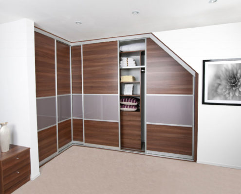
Typical Sliding Wardrobe Door Layout
- A Frame – Top Liner
- B Top Track
- C Frame – Strike Plates
- D Sliding Doors
- E Base Track
- F Frame – Bottom Liner
- G End Panel (optional)

2.Measuring
Please refer to the comprehensive measuring guide on our website:
www.wizardwardrobes/measuringupguide
Please measure carefully both the opening height and width in a minimum of three places. Please provide the smallest measurement for the height and the largest measurement for the width. If the height or width measurements vary by more than 15mm we recommend constructing a simple frame using strike plates and liners.
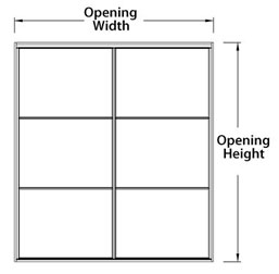
3.Tools & fixings you will need
| Tools | FIXINGS / MATERIALS |
| Electric Drill | Masonry Wall Plugs |
| Screwdriver | Wall and MFC Fixing Screws |
| Hacksaw | Cover Caps for Screws |
| Electric Jigsaw / Saw | Corner Blocks and/or Timber Battening |
| Spirit Level | |
| Set Square | |
| Plumb Line | |
| Wood Drill Bits | |
| Masonry Drill Bits | |
| Countersink Drill Bit | |
| Tape Measure | |
| Sand Paper | |
| Masking Tape |
4.Planning The Area
IMPORTANT – Before beginning construction check all relevant dimensions carefully. Check the area for water pipe and electric cables.
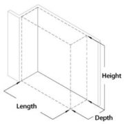
5.Constructing a frame
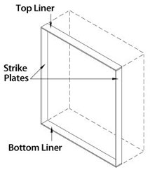
Constructing a frame will help with levelling, ease of fixing and will increase stability of the finished installation. Strike plates and liners are all provided free of charge as standard in the colour of your choice.
When cutting the strike plates and liners to length use masking tape along the cut lines to prevent the laminate surface from chipping. Carefully remove the tape after you have finished cutting.
Check all levels before final fixing.
6.Fitting an end panel (optional)
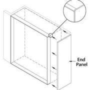
If you are not using the full width of an alcove, or constructing your wardrobe from a corner in the room, you will need to add an end panel. This can be attached to the strike plate, the floor, ceiling and back wall using fixing blocks, or with timber battening and screws.
If you are creating a wardrobe which will need a top panel adding, make sure the end panel is taller than the height of the frame by the thickness of the top panel so that the top panel will fit flush with the top edge of the end panel.
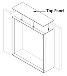
7.Fitting a top panel (optional)
If you are not using the ceiling of the room to create the ceiling of your wardrobe, you will need to add a top panel. This can be attached to the top liner, the side panel and back walls using fixing blocks, or with timber battening and screws.
If you are using screws to fix the top panel to the top liner of the frame, make sure the screw ends do not protrude through to the underside of the top liner as this will spoil the appearance and may prevent the top guide track being attached properly.
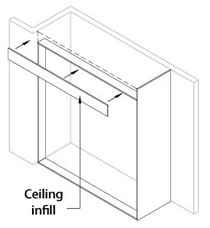
8. Fitting a ceiling infill (optional)
A ceiling infill panel can be used to make up the depth between the top of the frame and the ceiling of your room. This can be fixed to the top liner of the frame, the wall, end panel and ceiling using fixing blocks or with timber battening and screws.
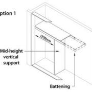
9. Internal Fittings – Vertical supports, shelves and hanging rails
Vertical supports to support internal shelving must be fitted at intervals of no more than 1200mm centers.
Set the vertical supports behind the door overlaps.
Cut the vertical support to length to go from the floor to the underside of the height you require your shelf. (usually between 1950mm and 2130mm) depending on your ceiling height.
After checking the supports are perfectly vertical they should be fixed securely to the wall using the brackets provided.
Shelving can then be attached to the walls, end panel and vertical supports using fixing blocks.
10. Cutting the tracks
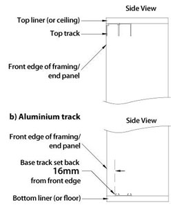
Carefully measure the width of your opening at the top and bottom. Deduct 2mm from each measurement and cut your top track and floor track to the correct length with a hacksaw. For positioning of tracks at Section A/A please see the next step 11.
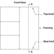
11. Positioning the tracks
Top track
Position the top track flush with the front edge of the frame. Mark on the top liner (or ceiling) where the screws for the top track will be positioned. Drill holes at 600mm intervals, and screw the top track in place. (Use cavity fixings if attaching the top track directly to the ceiling). Take care not to over tighten and distort the track length.
Base track
Position the base track 18mm behind the front of the top track. Mark on the bottom liner (or floor) 18mm back, offer the bottom
track you have cut into position to check its length. Drill pilot holes in the base track at 600mm intervals, and screw the base track in place. Take care not to over tighten and distort the track length.
12. Installing the doors
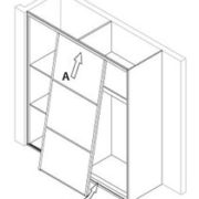
Install the rear doors first. Fully insert the door into the top track (A), taking care not to damage the bottom rollers. Align the bottom rollers with the base track (B) and slowly lower the door wheels into the track groove. After the door is in position, engage the spring by moving the small white tab away from the adjustment screw on the top of the wheel housing.
13. Doors and tracks
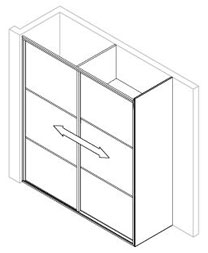
Make sure the doors and tracks are positioned parallel and level. Check both doors travel smoothly along the entire width. Follow the next steps to make final adjustments.
14. Adjustment
Bottom Roller
Make sure each door sits flush with the wall and/or other doors by raising and lowering the left and right sides of the door. The door level above the base track can be raised or lowered by adjusting the screw on the bottom rollers, using a screwdriver.
To move the doors down Turn clockwise To move the doors up Turn anti-clockwise

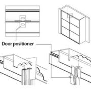
15. Fixing the door positioners
With the doors closed scribe in pencil a centre line on the top track where the centre of the door roller rests.
Place the door positioner central to this line.
Peel back the tape to reveal the double sided tape and stick the positioner so the groove is central to the centre of the wheel.
